


为了让您在我们网站上感受到更好的体验,我们强烈建议您将现有的IE浏览器升级到最新版本,或选择其它浏览器来访问我们的网站。
您可在此下载主流浏览器:

Google Chrome

Firefox

IE11
100G 光模块,长距离传输,单模最大传输距离10km


| Parameter | Symbol | Min | Max | Units |
| Supply Voltage | Vcc | -0.3 | 3.6 | V |
| Input Voltage | Vin | -0.3 | Vcc+0.3 | degC |
| Storage Temperature | Tst | -20 | 85 | ℃ |
| Case Operating Temperature | Top | 0 | 70 | ℃ |
| Humidity (non-condensing) | Rh | 5 | 85 | % |
| Damage Threshold, each Lane | TH | 5.5 | dBm |
| Parameter | Symbol | Min | Typical | Max | Units |
| Operating Case Temperature | Tca | 0 | 70 | ℃ | |
| Power Supply Voltage | Vcc | 3.13 | 3.3 | 3.47 | V |
| Date Rate, each Lane | fd | 25.78125 | Gb/s | ||
| Humidity | Rh | 5 | 85 | % | |
| Power Dissipation | P | 3.5 | W | ||
| Link Distance (G652D SMF) | D | 0.002 | 10 | KM |
| Parameter | Symbol | Min | Typical | Max | Units |
| Power Consumption | P | 3.5 | W | ||
| Supply Current | Icc | 1.06 | A | ||
| Transceiver Power-on Initialization Time | 2000 | ms | |||
| Transmitter (each Lane) | |||||
| Single Ended Input Voltage Tolerance | -0.3 | 4.0 | V | ||
| AC Common Mode Input Voltage Tolerance | 15 | mV | |||
| Differential Input Voltage Swing Threshold | 50 | mVpp | |||
| Differential Input Voltage Swing | Vin | 900 | mVpp | ||
| Differential Input Impedance | Zin | 90 | 100 | 110 | Ohm |
| Receiver (each Lane) | |||||
| Single Ended Output Voltage | -0.3 | 4 | V | ||
| AC Common Mode Output Voltage | 7.5 | mV | |||
| Differential Output Voltage Swing | Vout | 300 | 850 | mVpp | |
| Differential Output Impedance | Zout | 90 | 100 | 110 | Ohm |
| Parameter | Symbol | Min | Typical | Max | Units |
| Lane Wavelength | L0 | 1294.53 | 1295.56 | 1296.59 | nm |
| L1 | 1299.02 | 1300.05 | 1301.09 | nm | |
| L2 | 1303.54 | 1304.58 | 1305.63 | nm | |
| L3 | 1308.09 | 1309.14 | 1310.19 | nm | |
| Transmitter | |||||
| Side Mode Suppression Ratio | SMSR | 30 | dB | ||
| Total Average Launch Power | Pt | 10.5 | dBm | ||
| Average Launch Power, each Lane | Pavg | -4.3 | 4.5 | dBm | |
| Optical Modulation Amplitude (OMA), each Lane | Poma | -1.3 | 4.5 | dBm | |
| Difference in Launch Power between any Two Lanes (OMA) | Ptx, diff | 5.0 | dB | ||
| Launch Power in OMA minus TDEC, each Lane | -2.3 | dBm | |||
| Extinction ratio | ER | 4 | dB | ||
| Optical Return Loss Tolerance | TOL | 20 | dB | ||
| Transmitter Eye Mask Definition {X1, X2, X3, Y1, Y2, Y3}, | {0.25, 0.4, 0.45, 0.25, 0.28, 0.4} | ||||
| Average Launch Power OFF Transmitter, each Lane | Poff | -30 | dBm | ||
| Receiver | |||||
| Damage Threshold, each Lane | THd | 5.5 | dBm | ||
| Total Average Receiver Power | 10.5 | dBm | |||
| Average Receive Power, each Lane | -10.6 | 4.5 | dBm | ||
| Receive Power (OMA), each Lane | 4.5 | dBm | |||
| Receiver Sensitivity (OMA), each Lane | SEN | -8.6 | dBm | ||
| Stressed receiver Sensitivity (OMA), each Lane | -6.8 | dBm | |||
| LOS Assert | LOSA | -18 | dBm | ||
| LOS Deassert | LOSD | -15 | dBm | ||
| LOS Hysteresis | LOSH | 0.5 | dB | ||
| Conditions of Stress Receiver Sensitivity Test | |||||
| Vertical Eye Closure Penalty, each Lane | 1.8 | ||||
| Stressed Eye J2 Jitter, Lane under Test | 0.3 | UI | |||
| Stressed Eye J9 Jitter, Lane under Test | 0.47 | UI | |||
| Model | Name | Description |
| SUN-QSFP28-100G-LR4 | Optical Transceiver | QSFP28, 100Gbps, 1310nm; SM, dual fiber, max transmission distance: 10km; LC interface |
| SUN-QSFP28-100G-LR4-I | Optical Transceiver | QSFP28, 100Gbps,1310nm; SM, dual fiber, max transmission distance: 10km; LC interface, Industrial |

SUN-GYFJH 室外拉远光缆跳线
型号:SUN-GYFJH
插损低,防水、防尘

SUN-GYDGS 骨架槽带纤光缆
型号:SUN-GYDGS
GYDGS骨架槽带纤光缆,骨架式结构,金属加强芯,PE护套
Features
 具有良好的机械性能和温度特性 骨架式结构抗侧压性好,对光纤带有良好的保护 钢丝中心加强芯保证光缆的抗拉强度 全干式阻水结构 光纤组装密度高
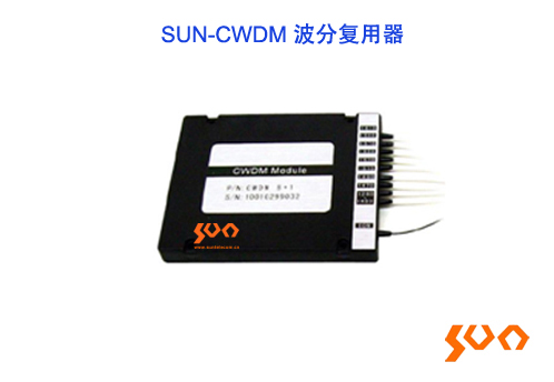
SUN-CWDM 波分复用器
型号:SUN-CWDM
CWDM,通道隔离度高,最多18个通道
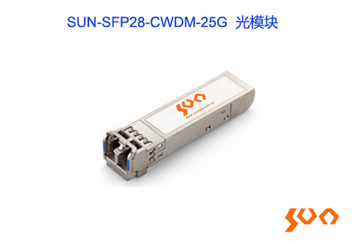
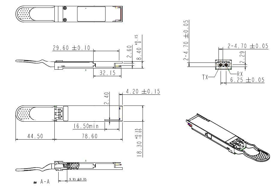
SUN-SFP28-CWDM-25G 光模块
型号:SUN-SFP28-CWDM-25G
25G 光模块,CWDM,长距离传输,单模最大传输距离10km
Features
1270~1370 CWDM波长可选 SFP28封装,LC接口 单模最大传输距离10km(单模光纤) 内置数字诊断功能 符合 SFF-8472 标准 工作温度:非工业级:0~+70°C 工业级:-40~+85°C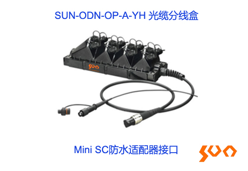
SUN-ODN-OP-A-YH 光缆分线盒
型号:SUN-ODN-OP-A-YH
最多可装12个ODVA/Mini SC/ODC/H-connector适配器
Features
高兼容性:ODVA, Mini SC, ODC, H-connector防水适配器可选 工厂密封或现场组装 1200N长期拉力 6到12个防水适配器接口适合各种单芯或多芯防水连接器 PLC可用 ip68防水等级 壁挂、高空安装或抱杆安装 符合IEC 61753-1标准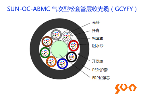
SUN-OC-ABMC 气吹型松套管层绞光缆(GCYFY)
型号:SUN-OC-ABMC
GCYFY室外光缆,气吹型,松套管层绞,FRP加强芯,PE护套
Features
具有良好的机械性能和温度特性 松套管材料具有良好的耐水解性能和较高的强度 良好的柔软性 FRP加强芯保证光缆的抗拉强度 缆径小,重量轻,适合气吹敷设方式
SUN-SFP28-25G-BIDI 光模块
型号:SUN-SFP28-25G-BIDI
25G 光模块,单纤双向,长距离传输,单模最大传输距离10km
Features
单纤双向 SFP28封装,LC接口 单模最大传输距离10km(单模光纤) 内置数字诊断功能 符合 SFF-8472 标准 工作温度:非工业级:0~+70°C 工业级:-40~+85°C
SUN-SFP28-25G-LR 光模块
型号:SUN-SFP28-25G-LR
25G 光模块,长距离传输,单模最大传输距离10km
Features
SFP28封装,LC接口 单模最大传输距离10km(单模光纤) 内置数字诊断功能 符合 SFF-8472 标准 工作温度:非工业级:0~+70°C 工业级:-40~+85°C


 dcs@suntelecom.cn

 821762075
 13671595619/15317399825


 dcs@suntelecom.cn
 中国 上海 金山工业区夏宁路666弄145号